System Details
The following is a detailed description of our helium recovery system along with questions I had when planning this system and things I would do differently now that I have more experience. I hope this is useful for those looking into a recovery system for their own facility. For information about installation costs and operating costs, see this page.
Recovery system installed: Jan 2021
Last update to this page: Sep 2023
The Cryomech System:
The overall footprint of our CryoMech system is just under 250 square feet (roughly 14 ft by
18 ft).
• Atmospheric Pressure Recovery Bag (300 ft3)
300 cubic feet of He gas is equivalent to roughly 11 L of LHe. However, the recovery compressor kicks on before the bag fully inflates and turns off before the bag is completely empty. With the recommended level-sensor settings, the amount of gas that’s pumped out of the bag between the top-level sensor turning the compressor on and the low-level sensor turning the compressor off is about 9 L of LHe. The gas plume collected while filling a magnet typically exceeds this volume, so it’s important to start the compressor before the top-level sensor is triggered and to adjust your LHe transfer rate so it’s roughly the same as the compressor rate.

- Recovery compressor (5.5 kW, 30A 3Ph)
When filling magnets in the same room as the collection system, I turn on the compressor manually just after the fill begins. Using the flowmeter in the manifold (Omega FL7611), I’ve found that adjusting the LHe transfer rate so the He gas plume is near 4.0 on the flowmeter matches the rate of the recovery compressor. Note, this flowmeter scale is in SCFM air and the specs for the compressor claim a rate of 8.5 SCFM for He; that’s a ratio of 2.1, which is 20% lower than the correction factor of 2.7 that’s typically quoted for He gas vs air with float style rotameters. This is within expectations considering the factor of 2.7 is itself based on an approximation and is calculated for standard T and P.
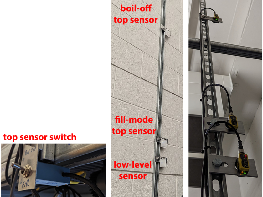
Several of the magnets connected to the recovery system are on different floors of the building, so there’s not a convenient way to manually start the recovery compressor or monitor the collection bag during the LHe transfer. To improve this situation, I wired up a switch box that connects two top-level sensors at different positions to the compressor cable for the top sensor. I can engage the upper top-level sensor for normal boil-off (i.e., slow He gas collection, trigger when the bag is almost full) or I can engage the lower top-level sensor that’s positioned about 6” above the low-level sensor when filling a magnet (i.e., high He gas flow, trigger when the bag is just starting to inflate).
Practical Notes:
- My CryoMech System came with ATC 7703 IR sensors which use 4 conductor M8 quick connects. These IR sensors are no longer available and CryoMech has switched to using Banner Engineering QS30LLPQ IR sensors which use 5 conductor M12 quick connects.
- The older ATC sensors work great with both retroreflective tape and retroreflectors. However, with the distances required by the collection bag, the Banner Engineering sensors do not perform reliably with retroreflective tape, not even the retroreflective tape sold by Banner Engineering (BRT-TVHG-2X2)! They do perform reliably with retroreflectors (BRT-51X51BM).
- The IR level sensors can go out of alignment with the reflectors, so it’s worth checking this alignment regularly. If the top-level sensor is out of alignment, the compressor will fail to turn on when the bag is full. The bag is equipped with a 0.15 psi safety valve, so this won’t damage any equipment, but it will lead to loss of He gas. On the other hand, if the low-level sensor is out of alignment and the compressor fails to turn off, the compressor will put a vacuum on the collection line which could put a vacuum on the magnet cryostats! To avoid this dangerous situation, it’s recommended that back-pressure regulators be placed in the manifold between the magnets and the recovery lines. In addition to this, the recovery compressor can be adjusted so that it shuts off if the inlet pressure is too low. See the instructions posted by the NMR facility at Georgia Tech.
Recovery Compressor (5.5 kW, 30A 3Ph)
This is the loudest part of the setup; for this reason, I don’t recommend placing it in the NMR facility. I put mine in an adjacent room and had holes drilled in the wall for the control and transfer lines. The compressor generates a lot of heat, so make sure you have a space that can deal with the heat load. I initially tried putting this compressor in a doghouse to reduce the noise, but that led to overheating, even with large fans built into the doghouse to force cooling air through the doghouse.The compressor has a water adsorber on it to protect the purifier. The air here in Utah is rather dry and the primary way that air enters my system is when I disconnect/reconnect the vent lines to the transfer dewars; because of this, I only need to regenerate the adsorber once every 2 months. Depending on humidity and how you use your setup, you may need to regenerate the adsorber every month or every few weeks.

Medium Pressure Storage Tanks (x8)
At the maximum pressure (400 psig) these tanks hold the equivalent of about 16 L LHe, so that’s a storage capacity of 128 L of LHe in gas form. This is more capacity than I really need for gas storage. The six magnets and two transfer dewars on my system boil off about 9 L of LHe per day. When filling a magnet cryostat, I consistently observe a flash of about 25%, so even emptying a 100 L transfer dewar during a fill will only produce flash vapor from about 25 L of LHe. Extra gas storage is primarily useful if there are long time periods where the purifier or LHeP are turned off for significant periods of time.Practical note: My facility only had a little floor space available, but it has tall ceilings. To make best use of the space available, I put the recovery bag on a shelf above the storage tanks. This has the added advantage of keeping the recovery bag out of reach so curious people don’t play with it.
Automatic Purifier (PT60 cold head)
This uses a cold head instead of a LN2 bath for the purifier cold trap and the convenience is quite nice. The purifier automatically warms up to purge and pump the trap as necessary. This saves a lot of time and money relative to the traditional LN2 bath purifier.Practical Notes:
- It’s worth keeping in mind that it takes 6-8 hours for the purifier to fully cool down, so it’s only worth turning off the purifier if you have a sufficiently long gap where you aren’t liquefying He. If you plan to have the purifier turned off for extended periods of time, it’s useful to have a larger volume of gas storage (see discussion above).
- I tested the purifier’s standby mode when I wasn’t actively liquifying He. This keeps the trap cold and I expected it to resume liquefying without the long cooldown time that’s needed after turning the purifier off. However, in my experience, the purifier always switches to the warm-up/trap-purge mode shortly after resuming from standby, so this really doesn’t provide any benefit over turning the purifier off. If the goal is simply to avoid emptying the storage tanks, (e.g., to keep enough pressure in the storage tanks for an upcoming transfer of LHe to a transfer dewar), I find it’s better to simply close the on/off valve on the LHeP inlet.

Initially, I struggled with the trap regeneration happening too frequently or the purifier not being able to reach “Steady State Purification Mode” after a trap regeneration. There are two common reasons for this:
- Over time, the ground pin gets corroded. I’ve had to replace the ground pin on my purifier about every 9 months.
- This behavior also happens when the outer vacuum space around the cold head goes soft. I’ve had to pump this vacuum space down about every six months.
- Over time, the ground pin gets corroded. I’ve had to replace the ground pin on my purifier about every 9 months.
- The purifier water adsorber. If you keep up with the regeneration of the water absorber on the recovery compressor, this adsorber stays dry for a long time. So far, I have had to regenerate this water adsorber every 12 months.

Liquid He Plant, LHeP22 (PT15 cold head) with 150 L Collection Dewar
- The nominal liquefaction rate for this LHe plant is 22 L/day. Mine has consistently performed at 25 L/day over the past two and half years. It’s not as loud as the recovery compressor, but it is significantly louder than the typical background noise of the NMR lab. It’s loud enough that it often startles students in the NMR facility when the cold head turns on.
- Practical Notes:
- Starting with a warm collection dewar and a warm cold head, it takes about 50 hours to cool the system down to the point where LHe begins collecting. Because of this, it’s simpler to keep the LHeP cold rather than cycling it between cold and warm between fills. The LHeP has an “on/off” mode that allows the liquid in the collection dewar to passively cool the system through boil off until the head pressure reaches 8 psig; at that point, the cold head turns on until the head pressure reaches ~0.6 psig where it turns off again. This runs the LHeP at a duty cycle of ~40%.
Unfortunately, the collection dewar does not have a heater to help push the LHe out when filling up a transfer dewar. (Technically, there is a heater, but it’s not easy to access or use, in my opinion.) Instead, I use push gas to help the LHe transfer proceed at a reasonable rate. One approach is to connect a gas cylinder to a port on the top of the LHeP; however, trace impurities will ice up on the cold head over time and this is the easiest way to reduce the LHeP performance; to avoid this, you need to use expensive UHP He gas as the push gas. To avoid that, I always keep enough gas in the storage tanks that I can use the pressure supplied by the purifier to help push the LHe out of the LHeP (the purifier supplies 30 psi to the inlet regulator on the LHeP). This approach does require some fiddling with the inlet regulator to gradually increase the pressure during the LHe fill as the back pressure increases during the transfer. For example, I typically start with the collection dewar at 3 psi and gradually ramp that up to about 5 psi by the end of the transfer. With this approach, I can transfer about 90 L of LHe in one hour with a flash of about 25%.
Flash Vapor
- When transferring LHe from one container to another, there is some percentage of the liquid converted to gas. This is the flash vapor and is quoted as a percent of the volume being pushed out of the storage container. For example, I consistently observe a flash of 25% when filling transfer dewars; if I push 100 L of LHe out of the collection dewar into a cold transfer dewar, I only expect 75 L of LHe to collect in the transfer dewar and the other 25 L to flash into gas that is collected by the collection bag and recovery compressor. This is the source of the He plume when filling a magnet cryostat.
- The origin of flash vapor is two-fold: the pressure drop alone leads to a significant amount of flash due to the sudden decrease in boiling T with the drop in external P above the liquid; the other source is heat leaks along the transfer path that contributes to vaporization of the LHe (this should be small with a good transfer line, but just pre-cooling the transfer line vaporizes about 1 L of LHe). This means that a higher pressure of push gas will lead to a faster transfer; but, the larger pressure drop will also lead to a higher flash % which, in turn, makes the fill a bit longer. However, too low of a push gas pressure leads to a very slow transfer and that allows the heat leaks to vaporize more LHe during the transfer. In my experience, a pressure drop of 3-4 psi is a good balance between the transfer rate and the pressure-drop induced flash.

Equipment Used with the CryoMech LHe Plant:
- Floor Scale (Optima 917)
Plan ahead so you have enough floor space for a good quality floor scale that sits next to the LHeP for monitoring transfer dewar fills. Ideally, you want a scale with a shallow ramp and plenty of space for moving the transfer dewar on and off the scale. Somehow, this completely escaped my attention during planning and I ended up with very limited space and funds when I finally purchased the scale. This scale works fine and was not expensive, but there are two significant annoyances: first, the ramp is steeper than ideal and it requires some wrestling to get a transfer dewar on/off the scale; second, this scale only reads ±0.5 lb which is about ±2 L of LHe. A resolution of at least ±0.1 lb would give more accurate readings and improve my estimates of the LHe volume that I transfer during fills. - Vacuum Pump (Edwards nXDS6i + Kurt Lesker 275i Pirani gauge)
I didn’t have experience regenerating water adsorbers and didn’t have any pumps in my facility before getting the recovery system. Because of this, I purchased a simple scroll pump that has maximum achievable vacuum of ~25 mTorr. I would recommend against this. While I’m technically able to regenerate the adsorbers, even after 4 weeks I’m not quite able to get down to the recommended pressure. Furthermore, when pumping the vacuum space around the cold head in the purifier, you really need a turbo pump to reach the recommended vacuum. LHe Transfer Dewar (Cryofab CMSH-100)
I have two 100 L transfer dewars. The standard dewar has an average boil-off of ~1.3 L/day whereas the one with a built-in heater has an average boil-off of ~2.1 L/day. These can easily go 6 weeks between topping them off to keep them cold. Depending on your fill schedule, you can simply top off the transfer dewar after a magnet fill and then top it off once or twice over the next 3-4 months before the next magnet fill. However, this requires having enough excess He in your recovery system that you have LHe on hand to top off the transfer dewar after a magnet fill. I recommend keeping the transfer dewar cold via passive LHe boil off rather than letting the dewar warm up and trying to cool it down before a fill. It’s very time consuming to cool down a warm dewar and this process also vaporizes a lot of LHe.To capture the He gas that boils off from these transfer dewars (and to collect the He gas when venting the transfer dewars during a fill) you need a vent line and a port in the collection circuit for the vent line by each magnet and by the LHeP. My original setup used extreme air hoses with ½” JIC flare fittings (McMaster-Carr 50675K176 and 5676T12). However, I didn’t like how much air (and moisture) could get in the vent line every time I had to disconnect a vent line. I now use Parker EA series double-shut-off quick connects on the extreme air hoses to minimize how much air/moisture gets into the recovery system when disconnecting the vent line to move the dewar around (Parker BVEAN8-8F, BVEAN8-8M, BVEAC8-8F, BVEAC8-8M and McMaster Carr 5676T33). These quick couplers are designed to be liquid and gas tight under 0.99 bar of vacuum as well as 1500 psi of pressure with a maximum spillage volume of 4.2 mL. My leak testing shows no observable He leaks when these quick connects are at room temperature (coupled or uncoupled). However, when filling a transfer dewar, the vent line ices up and remains iced up for most of the transfer; under these conditions, I can detect a He leak, but it’s not excessive.


The He Collection Circuit:
- Main Collection Circuit
The main collection circuit is assembled from 1” capped and cleaned Cu tube connected with Pro-Press fittings. The recovery system is in the basement of the chemistry building in the same room as the NMR facility (3 magnets). Another magnet is also in the basement, but down the hallway, and two more magnets are up on the 3rd floor. Consequently, the collection circuit required a lot of Cu tubing to connect all six of these magnets to the collection bag. Note: even with 1” tube, there’s a noticeably higher back pressure on the magnets upstairs. If possible, I recommend 2” tube for more distant magnets to reduce the pressure drop. - I was initially skeptical of using Pro-Press fittings. Our physical facility prefers to use Pro-Press because it’s faster and cleaner than welding. It turns out that Pro-Press has a specific o-ring rated for He gas (HNBR, 21033 for 1” o-rings). These had to be ordered separately and swapped out for all the standard o-rings during assembly. Once the magnets were connected to the collection circuit, tests with a He leak detector show that these o-rings and Pro-Press fittings behave beautifully.

When first using the recovery system, keep in mind that there will be water adsorbed to the surface inside the pipes of the collection circuit as well as air in the lines. To remove this, I performed several rounds of pumping on the collection circuit and then purging it with He gas. I then pumped on the collection circuit for a several weeks. My initial leak test was pumping the collection circuit down to 25 mTorr and then monitoring the pressure for several weeks. There was no observable change in the pressure.
Another check on the quality of the collection circuit is the total loss rate of He from the collection system. I have detailed records of the total amount of He in the recovery system (transfer dewars, collection dewar, storage tanks, with an empty collection bag) before and after every LHe transfer (both for transfer dewar fills and magnet cryostat fills). Between June 2022 and June 2023, I pushed 5100 L of LHe out of the collection dewar, collecting 3900 L of LHe in 80 transfer dewar fills. During 55 magnet fills, I pushed 2700 L of LHe out of the transfer dewars, collecting 2100 L of LHe in the magnet cryostats. Over the course of that year, I only lost 210 L of LHe from the recovery system (comparing time points at the same position in the fill schedule). This yields a collection efficiency of 95% relative to the amount liquefied and pushed out of the collection dewar or 91% relative to the amount delivered for magnet fills. During this year, I was collecting the vent gas from the transfer dewar during fills, but I was not yet collecting the He lost from the pre-cool of transfer lines. My estimates for this year put the loss for transfer line pre-cool at about 1.5 L LHe and roughly 0.25 L of LHe during a transfer dewar fill. That leaves about 108 L of LHe lost through leaks over one year. With an expansion ratio of 750, that’s a loss of 154 mL per min of He gas from the entire system spanning 3 floors and connecting 6 magnets or roughly 26 mL per min of He gas per magnet. I’m hoping to improve this by collecting the He gas during the transfer line pre-cool step (see below) as well as improving the setup of one magnet that currently loses a lot of He during the fill.
I have some concerns about the long-term health of the o-rings in the Pro-Press fittings that experience thermal cycling during magnet fills (i.e., those in the line leading up to the heat exchanger). I’m not sure how justified this concern is; after all, the o-rings in the magnet turrets handle thermal cycling every week from LN2 fills and every few months from LHe fills. I will continue to monitor the annual loss rate moving forward as well as routinely checking those Pro-Press fittings with a He leak detector to check this.
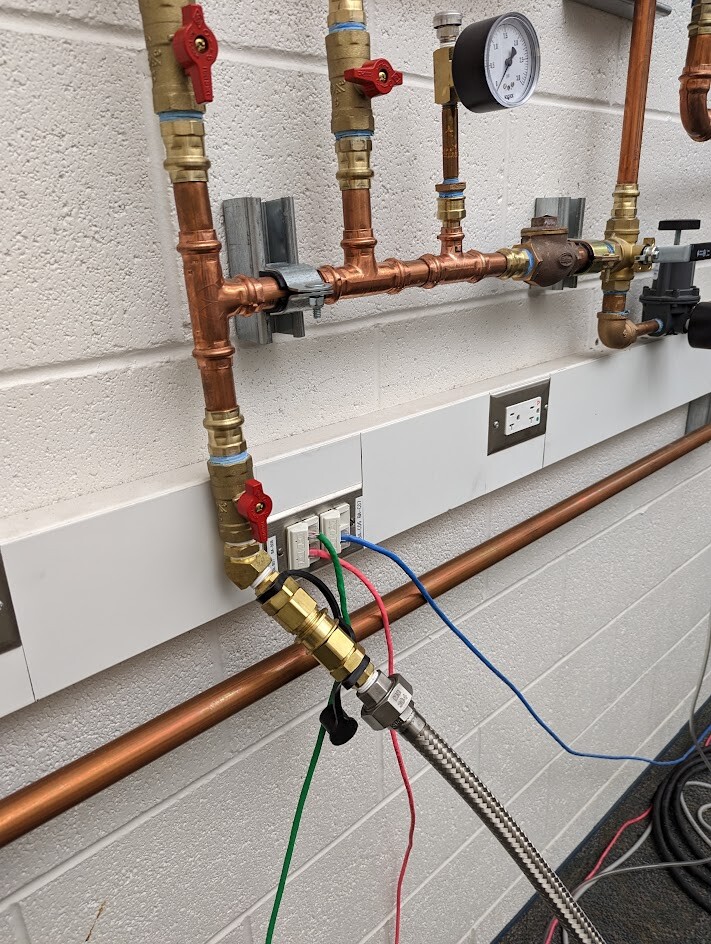
- Manifolds for Connecting Magnets to the Collection Circuit
I copied Yale’s design for the manifolds. Here is info for the major parts (along with some thoughts, when relevant):
Flow Meter, 0-8 CFM (Omega FL7611)
This works beautifully for monitoring the plume during a fill. To ensure that the flash gas doesn’t overfill the collection bag during a fill, I adjust the LHe transfer rate until this flowmeter reads 3.5-4.5 CFM, consistent with the rate of the recovery compressor.
During the planning stages, I was concerned about being able to recognize the endpoint of a magnet fill. I had only ever used the visible flame in the gas plume as the obvious endpoint for a fill which isn’t possible with the gas plume entirely contained in the collection circuit. When the magnet is full, the rapid increase in He gas entering the collection circuit causes the float to rise quickly to 8.0, making the endpoint unambiguous.Note: The pathway parallel to the flow meter was included due to reports that other facilities had observed He leaks at the flow meter. I have not observed any leaks here; consequently, I leave the valve on the parallel path closed and the valves before and after the flow meter open.
- Back-Pressure Regulator (Control Air Inc., 700BP; McMaster-Carr 4783K53)
As discussed above, a back-pressure regulator protects the magnets if the low-level sensor fails to turn off the recovery compressor and a vacuum is applied to the collection circuit. This also protects the magnets against over-pressure if the valve to the main collection circuit gets closed as well as insulating the cryostat from pressure fluctuations when filling another magnet and collecting the flash vapor with the collection system.

- One Way Valve (Eclipse 1006A Disc-Type Check Valve)
These swinging disc valves have very low cracking pressure, which minimizes the impact on the overall pressure drop (i.e., the pressure that the magnet cryostat experiences is the ambient pressure + the total pressure drop from the various check valves and the pipe of the collection circuit). These one-way valves are not gas tight against backflow; I have these in each manifold as a low impact quick and dirty safety measure – if a valve or KF25 fitting were to be left open to atmosphere, this would turn a large leak into a slow leak. - Safety Relief Valve & Pressure Gauge
As a safety measure, I include a pressure gauge (Circle Valve 25-210-5-PSI) for monitoring the pressure during a LHe transfer as well as check valve (Circle Valve 559B-2M-2) to ensure the manifold can’t over pressurize (e.g., if someone accidentally closed a valve leading to the main collection circuit).
Note: When in boil-off mode, this is a bit redundant as the back-pressure regulator already provides protection against over pressure. However, when in fill mode, this does provide some protection from excessive back pressure on the cryostat.
Note: When I first installed these, I used check valves with a cracking pressure of 1 psi. However, in practice, these would crack at 0.6 or 0.7 psi. I have now replaced these with check valves that have a cracking pressure of 2 psi; in practice, they crack closer to 1.5 or 1.6 psi.
- Heat Exchanger (Zephair ZAS057NZA-F, ZAS204NZA-F)
These are perfect for use with Pro-Press because of the 1” Cu ports. However, that the 8x8 size is too small, in my experience. I recommend the 20x24 or 22x22; possibly larger ones for magnets with larger LHe fill volumes. As shown in the image below, the small 8x8 heat exchanger isn’t sufficient to prevent the downstream pipe from freezing, especially for transfer dewar fills. The primary purpose of these heat exchangers is to protect the acrylic flow meter from being damaged by extreme thermal cycles during each magnet fill.

- KF25 Connections
The connection between a magnet and the collection manifold is made with KF25 fittings. A KF25 tee (Kurt Lesker, QF25-100-TAL) provides a path for the boil off and a path for the gas plume during a LHe fill. A KF25 flange to F NPT (Kurt Lesker, QF25XFNPT4A) provides the connection to the in-line check-valve that connects to the instrument’s boil off meter; for example, Varian DDR-era magnets have a 0.15 psi in-line check valve (Circle Valve 119B-3PP); and recent Bruker magnets have a 15 mbar in-line check valve (Bruker Z52395 and Z52523). A KF25 flex line (Kurt Lesker, MH-QF-B80) provides a large diameter path for the He plume during a fill. A KF25 flange to 1” nipple (Kurt Lesker, QF25-100-LFB) provides the connection via Pro-Press to the heat exchanger. The nipple isn’t quite the right size for Pro-Press, so we brazed the nipple to 1” copper tube and then use the Pro-Press fittings on the copper tube. Choosing the path (i.e., through the back-pressure regulator for boil or through the heat exchanger for a magnet fill) is done with the T-valve (McMaster-Carr 4093T24) in the manifold.


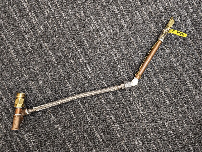
- Transfer Line Pre-Cool Sheath
I finally have a design that I’m happy with for collecting the He gas during the transfer line pre-cool step before a magnet fill. The pre-cool sheath needs to be flexible, so you can lift the long leg out of the LHe once the transfer line is cold while keeping the short leg in the sheath; but, it can’t be a material that freezes and becomes brittle once the transfer line flames. The sheath needs a valve that won’t freeze so you can remove the short leg and close the valve. It also needs an adapter for a gas tight fit around the short leg of the transfer line. A short length of extreme temperature air hose provides the flexibility (McMaster-Carr 5793T71, 18” length). The CryoFab upper stack (identical to what’s on top of the LHe transfer dewars) provides both a valve that won’t freeze shut as well as quick connects seal around the transfer line (CryoFab VALBALLIQ1/2, COUQUITHR1/2, COUQUITHR3/8). I use a 9” length of copper pipe (McMaster-Carr 4568K514) for the main sheath between the valve and the flex line to ensure that the transfer line doesn’t get bent or touch the sides of the pre-cool sheath. The rest of the connections are simple NPT unions, a 45°, a 90°, a wye adapter, and a 2” length of copper pipe to connect to the Parker quick connect (McMaster-Carr 50785K84, 4429K153, 4429K362, 4568K173; Parker BVEAC8-8F). This attaches to the vent line with a Parker quick connect on the other end (McMaster-Carr 5676T33, 120” length; Parker BVEAN8-8M).